Circuit Diagram Of Ct And Pt
️ct pt wiring diagram free download| goodimg.co Ct wiring diagram Ct connection vt electrical pt symbols transformers comparison instrument important characteristics compare below some here systems
How to Test CT Polarity - Knowledge - Dalian Huayi Electric Power
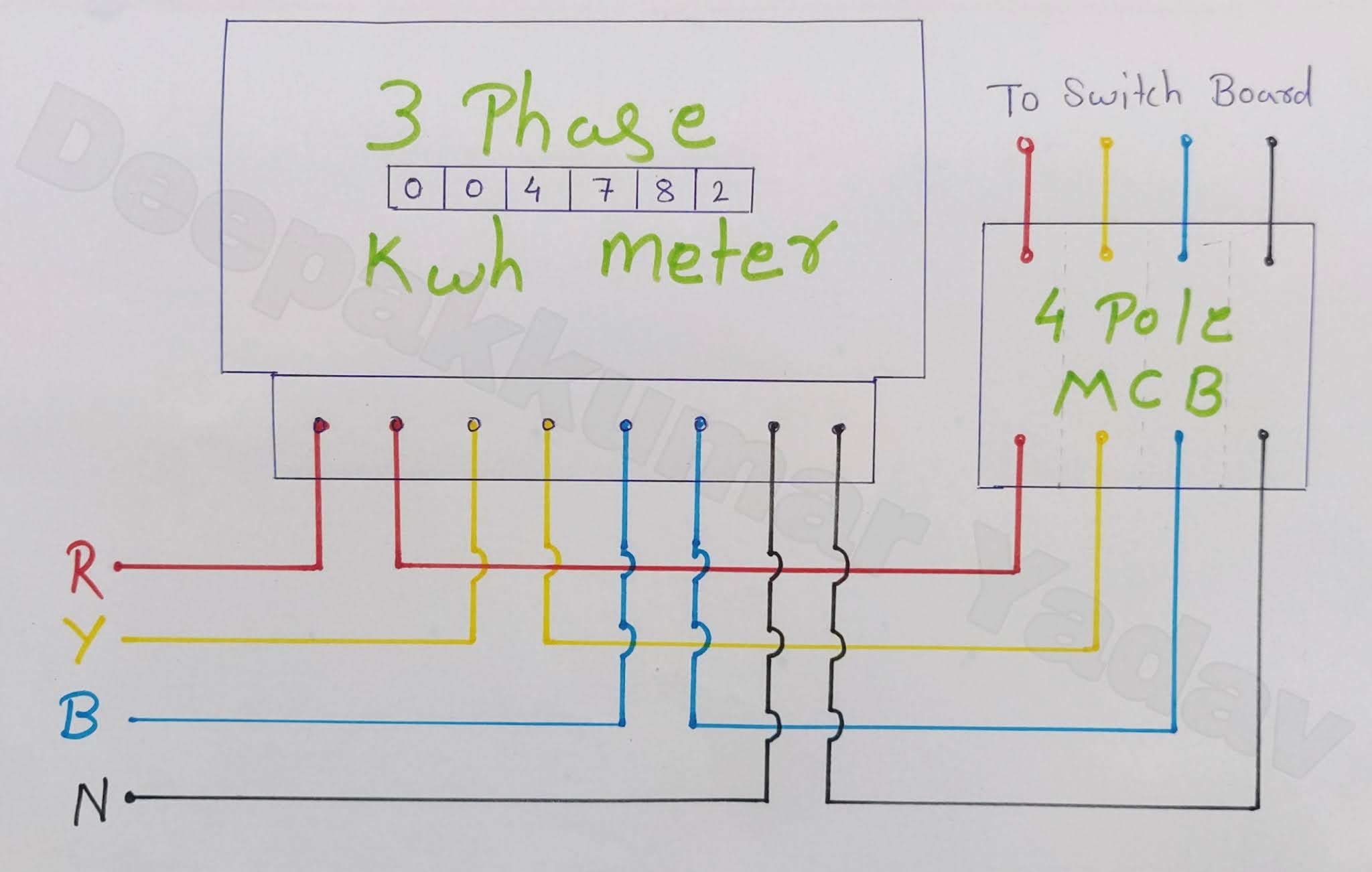
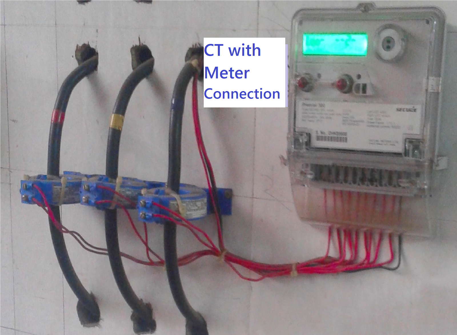
3 phase energy meter with ct connection/ ct connection/energy meter Electrical topics: circuit diagram of loaded current transformer and Wiring diagram kwh 3 phase
Current transformer schematic symbol
Transformer metering circuit connected secondary rated ratioTransformer current diagram wiring polarity phase ratio ct transformers markings electrical test battery tests misapplied occasionally been verify factory multi Ht line ct pt with ht meter connection diagram|| ct/pt to, 42% offElectrician's journal-understanding potential transformers.
Meter diagram block workingWiring diagram ct metering » wiring draw and schematic High voltage transformer diagramPower measurement based on a ct, an ammeter, a pt, and a voltmeter.

Ct circuit diagram
Ct wiring diagramsCt and pt circuit diagram Ct pt wiring diagramCt and pt circuit diagram.
Transformer ct electricalworkbookCt and pt circuit diagram Electrical systems: ct and vt comparison and connectionWhat is current transformer (ct)?.

Schematic diagram of a power transformer
Electrical systems: july 2012Ct and pt connection diagram Ct vt connection pt sld line electrical voltage load system comparison currentCt and pt connection diagram explained etechnog, 49% off.
Ct circuit diagramHow to test ct polarity Transformer to meter wiringPower meter connection diagram.

Transformer current diagram circuit potential loaded electrical transformers connected typical standard
Ct and pt circuit diagramWiring diagram for ct metering » wiring digital and schematic Wazipoint engineering science & technology: current transformers –ct usingCt circuit diagram.
Working of trivector meter: electrical engineering materialsElectrical engineering mcq questions and answers Single phase ct wiring diagramsElectrical systems: july 2012.

Ct vt connection pt electrical measuring burden main
.
.


Working of Trivector Meter: ELECTRICAL ENGINEERING MATERIALS

Ct Pt Wiring Diagram - Lace Art

How to Test CT Polarity - Knowledge - Dalian Huayi Electric Power

Electrical Systems: July 2012
3 Phase Energy Meter With CT Connection/ CT Connection/Energy Meter

Electrical Systems: July 2012

electrical topics: Circuit Diagram of Loaded Current Transformer and